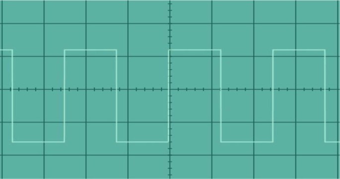

For this, a null method is used whereby the Helmholtz coil current and orientation are adjusted so as to produce zero net magnetic field at the location of the sensor. Magnetic dip angle are required, and these can be obtained from measurements using a single axis magnetic flux-gate sensor and a single Helmholtz coil that can be oriented in azimuth and in slant angle. The local total geomagnetic field intensity and The measurements required for corrections are made using rotations of the triad flux-gate package in the horizontal plane on a test stand using only the local geomagnetic field. These modulation techniques are also used for grid connected inverters 2. voltage outputs from the flux-gate electronic circuitry. Uni-polar PWM (UPPWM) and bipolar PWM (BPPWM) are very popular for single phase inverters 1. Computations then provide components of the local geomagnetic field along the orthogonal case-axes of the magnetometer as a function of the measured D.C. more It is difficult to accurately determine and place the individual magnetic axes of a 3-axis flux-gate magnetometer orthogonal to one-another and in-line with the orthogonal axes of the case in which these sensors are embedded.ĭerivations and procedures to remove these errors of misalignment and non-orthogonality are presented. Edited answer to reflect the same.It is difficult to accurately determine and place the individual magnetic axes of a 3-axis flux-g. If we let x 0 v t, where v is positive and t is time, then the displacement increases with increasing time. To displace any function f(x) to the right, just change its argument from x to x-x 0, where x 0 is a positive number. Higher harmonics cannot be generated (a band-pass filter would be required for the same).ĮDIT: Thanks to for pointing out that the question says square wave and not rectangular function. In the mathematical sense, a wave is any function that moves. However one is restricted to a sine wave with the frequency the same as the period ( $1/f_o$) of the input square wave. It is therefore viable to use a low pass filter to create a sine wave out of a square wave. Observing the magnitude plot, if one were to pick a low pass filter with cut-off frequency between that corresponding to bin #1 (1st harmonic: 100 Hz) and bin #2 (3th harmonic: 500 Hz), the other higher frequencies would get cut out and there would only be 2 frequencies that remain: -100 Hz and 100 Hz which would correspondingly represent a sine wave (as mentioned above).

(source: In the image attached above, the function on the left is a square wave and the one on the right is the magnitude plot of its corresponding Fourier transform (as mentioned before, the frequencies are actually complex numbers and the entire Fourier transform would be complete only with the addition of a "phase plot" as well). High frequencies which correspond to rapid transformations in the time domain are removed from the input and only the lower frequencies remain. Now, lets see what exactly a low pass filter does to a square wave.Ī low pass filter can be understood as a filter that cuts-off frequencies above a certain threshold when applied to some input. Basically, it may attenuate some parts of the frequency spectrum and magnify other parts, and may add a "phase change" (frequencies manifest themselves as complex numbers, and phase changes become relevant then) one-ninth of the amplitude and so on will provide an increasingly close fit to the square wave. A filter modifies the input and generates some output from it and is often represented in the frequency domain => A filter modifies the Fourier transform (aka frequency spectrum) of an input. The sine wave is a poor representation of the original. If you are clear with that, then let's move on to what a filter is. The mathematical representation of this approach is: s t 2b1 t 1 cos 2 fct 2b2 t 1 sin 2 fct (3. Then the first signal is multiplied by a cosine wave and the second is multiplied by a sine wave. The Fourier transform essentially represents the time-domain information stored in some function (a square wave in your case) in terms of frequencies.Ī simple example would be a sine wave $sin(2\pi f_$ (the negative value occurs because of the mathematical representation of the Fourier transform using complex exponentials, but nevertheless the positive frequency $f_c$ is what one would expect). sequences are scaled between -1 and +1 for bipolar signals. To be able to analyze what a low pass filter does first you would need to understand what a Fourier transform is, hence some theory first.


 0 kommentar(er)
